Categories
Aims Problems Subject

Chapter 11: Structural members – Beams – Problems

After reading previous entry and understanding the meaning of isostatic beam, shear force, bending moment, how to apply method of sections, you should try to solve next exercises.

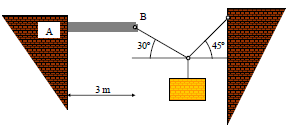
EXERCISE 1: A cantilever beam AB with mass 100 kg is subjected by cables as shown in figure. If the moment acting on the beam at A is greater than 2400 kN·m, beam will give way at A.

a) Determine the maximum weight of the load suspended by the two cables.

b) Draw shear and moment diagrams specifying values at all change of loading positions and at points of zero shear.

EXERCISE 2: Draw the shear-force and bending-moment diagrams for the loaded beam and determine the maximum moment M and its location x from the left end.

Categories
Aims Subject

Chapter 11. Structural members: beams

Chapter 11. INTERNAL FORCES IN STRUCTURAL MEMBERS: ISOSTATIC PLANE BEAMS

11.1 Isostatic beams. Introduction.

11.2 Reactions at supports.

11.3 Types of loads on beams.

11.4 Internal forces in beams. Sign convention.

11.5 Loads, shears and axial forces.

11.6 Bending moments.

11.7 Graphical analysis of a beam.

11.8 Elastic curve of a beam.

You should learn to solve any isostatic plane beam after the theoretical lectures, the problem sessions and the homework you did during this part of the subject. Chapter objectives can be summarized as follows:

  • To show how to use the method of sections to determine the internal loadings in a member.
  • To generate this procedure by formulating equations that can be plotted so that they describe the internal shear and moment throughout a member.
  • To draw the shear and moment diagrams for any isostatic plane beam.

The next video explains how to solve a beam using the method of sections (Spanish from a Professor at the Universitat Politècnica de València).

https://media.upv.es/#/portal/video/74c39eb3-0e90-504d-80f2-9664a5f4b92a

Bibliography

Rodes Roca, J. J., Durá Doménech, A. i Vera Guarinos, J., Fonaments físics de les construccions arquitectòniques (Publicacions de la Universitat d’Alacant, Alacant, 2011). Capítol 12.

Rodes Roca, J. J., Exercicis i problemes dels fonaments físics d’arquitectura. I. Vectors lliscants i geometria de masses (ECU, Alacant, 2009)

Rodes Roca, J. J. i Durá Doménech, A., Exercicis i problemes dels fonaments físics d’arquitectura. II. Estàtica aplicada a les estructures (Col·lecció Joan Fuster 154, Universitat d’Alacant, 2013)

Tipler, P. A. i Mosca, G., Física per a la ciència i la tecnologia, Volum 1 (Reverté, Barcelona, 2010). Capítols 1 i 12.
Categories
Aims Problems Subject

Chapter 9: Elasticity – Problems

After reading previous entry and understanding the meaning of stress and strain, how to apply Hooke’s law to elastic solids, you should try to solve next exercises.

EXERCISE 1: A steel wire has a length of 25 m and its cross-sectional area is 6 mm × 0.8 mm. Considering the effect of its own weight negligible, calculate the strain and the change in length when we applied a tension force of 6 kp. Young’s modulus of steel is 2.1×10^6 kp/cm^2.

EXERCISE 2: Determine the elongation of a bar of uniform cross section S and length L which is hanging and subjected to its own weight.


Categories
Aims Subject

Chapter 9. Elasticity

Chapter 9. MECHANICAL PROPERTIES OF SOLIDS.

9.1 Elastic behaviour of solids.

9.2 Method of sections.

9.3 Normal stress and shear stress.

9.4 Axial deformation: Young’s modulus.

Objectives:

  • Demonstrate your understanding of elasticity, elastic limit, stress, strain, and, ultimate strength.
  • Write and apply formulas for calculating Young’s modulus, shear modulus, and, bulk modulus.
  • Solve problems involving deformation in members of loaded trusses.

http://www.slideshare.net/ahsanlatif19/elasticity-28486442

Bibliography

Rodes Roca, J. J., Durá Doménech, A. i Vera Guarinos, J., Fonaments físics de les construccions arquitectòniques (Publicacions de la Universitat d’Alacant, Alacant, 2011). Capítol 10. (There is also a version in Spanish of this book)

Rodes Roca, J. J., Exercicis i problemes dels fonaments físics d’arquitectura. I. Vectors lliscants i geometria de masses (ECU, Alacant, 2009)

Rodes Roca, J. J. i Durá Doménech, A., Exercicis i problemes dels fonaments físics d’arquitectura. II. Estàtica aplicada a les estructures (Col·lecció Joan Fuster 154, Universitat d’Alacant, 2013)

Tipler, P. A. i Mosca, G., Física per a la ciència i la tecnologia, Volum 1 (Reverté, Barcelona, 2010). Capítols 1 i 12. (This is the catalan version of the original English book)

Categories
Aims Problems Subject

Chapter 6: Equilibrium of rigid bodies (III). Distributed forces – Problems

After reading previous entry and understanding the meaning of distributed forces, how to calculate the equivalent resultant to the distributed load, you should try to solve next exercises.

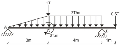
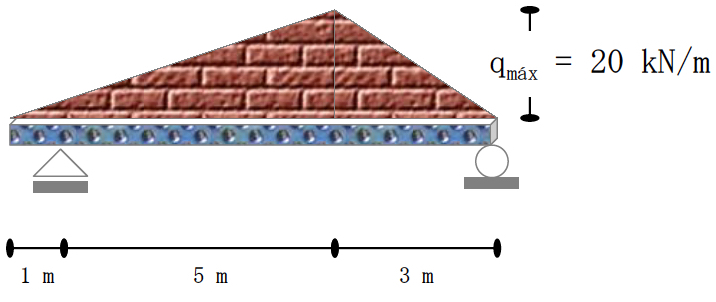
EXERCISE 1: Calculate the supports reactions at A and B for the beam subjected to the asymmetric load distributions.

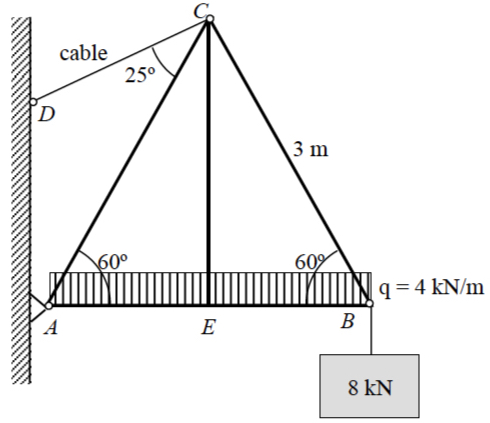
EXERCISE 2: The symmetric simple truss is loaded as shown. Determine the reactions at wall support A and the tension in cable CD.

Categories
Aims Subject

Chapter 6: Equilibrium of rigid bodies (III). Distributed forces

DISTRIBUTED FORCES

In the previous sections we treated all forces as concentrated along
their lines of action and at their points of application. This treatment provided a reasonable model for those forces. Actually, “concentratedforces do not exist in the exact sense, since every external force applied mechanically to a body is distributed over a finite contact area, however small.

What is more, distributed forces are a particular case of a coplanar parallel system of forces. The body force due to the gravitational attraction of the earth (weight) is by far the most commonly encountered distributed force. Figure shows (Meriam & Kreige 7th edition):

  • Line distribution: When a force is distributed along a line, as in the continuous vertical load supported by a suspended cable, Fig. (a), the intensity w of the loading is expressed as force per unit length of line, newtons per metre (N/m).
  • Area distribution: When a force is distributed over an area, as with the hydraulic pressure of water against the inner face of a section of dam, Fig. (b), the intensity is expressed as force per unit area. This intensity is called pressure for the action of fluid forces and stress for the internal distribution of forces in solids. The basic unit for pressure or stress in SI is the newton per square meter (N/m2), which is also called the pascal (Pa).
  • Volume distribution: A force which is distributed over the volume of a body is called a body force. The most common body force is the force of gravitational attraction, which acts on all elements of mass in a body. The determination of the forces on the supports of the heavy cantilevered structure in Fig. (c), for example, would require accounting for the distribution of gravitational force throughout the structure. The intensity of gravitational force is the specific weight ρg, where is the density (mass per unit volume) and g is the acceleration due to gravity. The units for ρg are (kg/m3)(m/s2) N/m3 in SI units

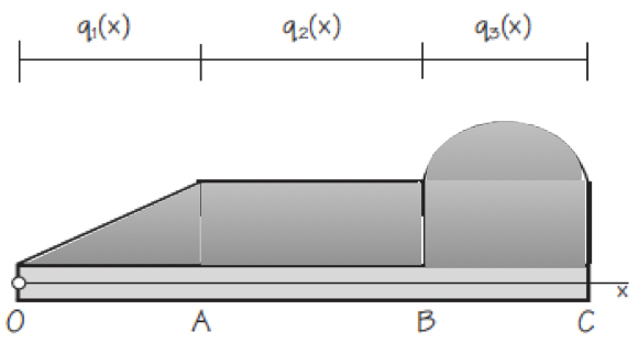
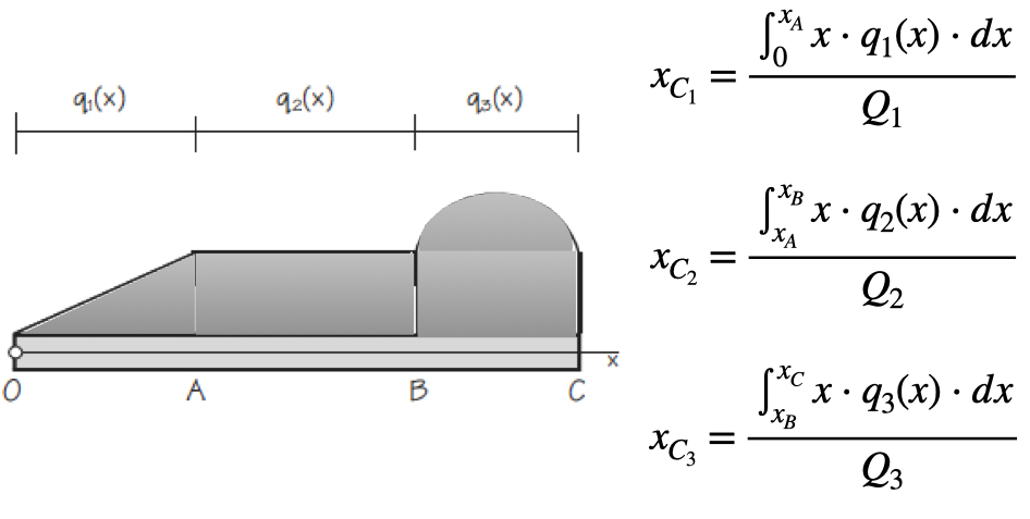
Figure shows a statically determinate beam that is supporting a general distributed load. The intensities qi(x) of a distributed load may be expressed as force per unit of length of beam. The intensity may be constant or variable, continuous or discontinuous. The intensity of the loading in Figure is constant from A to B and variable from O to A and from B to C. Although the intensity itself is not discontinuous at A and B, the rate of change of intensity dq/dx is discontinuous.Any distributed load can be replaced by a concentrated load with a magnitude equal to the area under the load curve and a line of action passing through the centroid of the area. Therefore, we need to determine the equivalent force of the distributed force, i. e. the resultant, and the centre of gravity where it will be applied. Once the distributed loads have been reduced to their equivalent concentrated loads, the external reactions acting on the beam may be found by a straightforward static analysis as developed in Chapter 6 (equilibrium).


Categories
Aims Problems Subject

Chapter 6: Equilibrium of rigid bodies (II). Stability – Problem

After reading previous entry and understanding the meaning of stability, rollover and stabilising moments, you should try to solve next exercise.

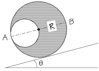
A homogeneous cylinder of radius R has a cylindrical hole of diameter R as shows in Figure. Cylinder can roll down the inclined plane without slipping. Determine the maximum angle θ of the inclined plane because the cylinder be in equilibrium. Obtain also the angle between the horizontal and the diameter AB in this situation.

NOTE: you can send your solution by tutorial tool in UACloud for including it in the continuous evaluation.

Categories
Aims Subject

Chapter 6: Equilibrium of rigid bodies (II). Stability

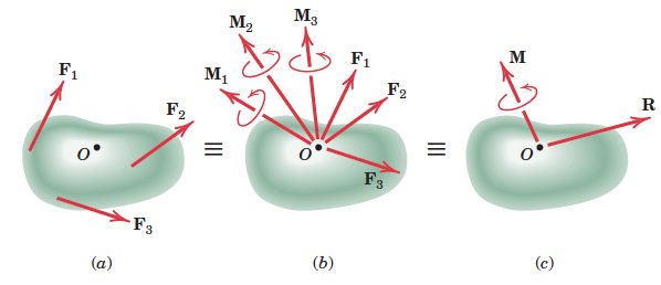
Any system of forces may be replaced by a resultant force R and a resultant moment (couple of a force) M at any point of the space. We call this couple vectors (R, M) as system “torsor”. Figure (from Meriam & Kraige 7th edition) shows a system of forces acting on a rigid body.

The point O selected as the point of concurrency for the forces is arbitrary, and the magnitude and direction of M depend on the particular point O selected. The magnitude and direction of R, however, are invariant, i.e. are the same no matter which point is selected.

If a system of forces acting on a body are such that the resultant force and resultant moment at point O are mutually perpendicular, the whole system can be replaced by a single force acting along a new line of action such that it causes the same moment with respect to O. We now examine the resultants for several special system of forces:

  • Concurrent forces: because there are no moments about the point of concurrency, system “torsor” at this point is only the resultant force R.
  • Parallel forces: not all in the same plane, the magnitude of the parallel resultant force R is simply the magnitude of the algebraic sum of the given forces. The position of its line of action is obtained from the principle of moments by requiring that r × R = MO. Here r is a position vector extending from the force–couple reference point O to the final line of action of R, and MO is the sum of the moments of the individual forces about O.
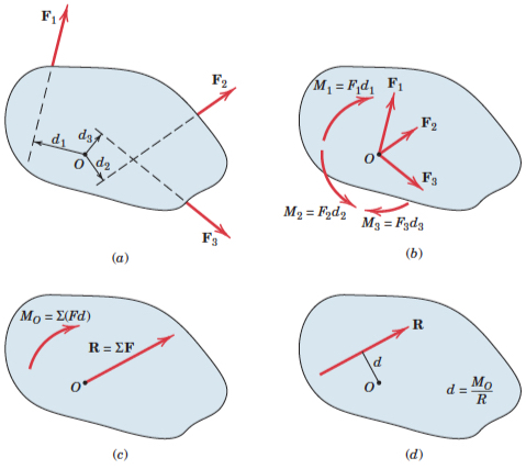
  • Coplanar forces: it may be reduced to only the resultant force R provided the line of action of R is passing through the centre of the system of forces, as shows Figure (rom Meriam & Kraige 7th edition):

STABILITY AND TOPPLING

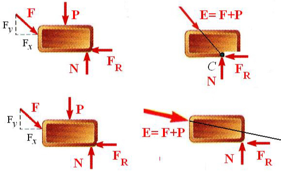
Let’s consider a 2D situation. A rigid body under the action of forces (which are necessarily coplanar) can only be in equilibrium if the system of forces seen in the free-body diagram can be reduced to three concurrent forces that meet at a point that is inside the body.

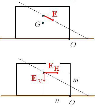
Three concurrent forces at point C which is inside the rigid body: EQUILIBRIUM (upper figure).Three non-concurrent forces inside the rigid body: THERE IS NO EQUILIBRIUM (bottom figure). Therefore, if a body is not in equilibrium, we can check if it is prone to overturning or stable against toppling. For this, we calculate the resultant of all external forces and draw it at the point where its line of action cuts the line of action of the weight. Assume the rigid body can rotate about point O, we call rollover moment the expression:

and stabilising moment the expression:

If the rollover moment is larger than the stabilising moment, the rigid body will turn over.


Categories
Aims Subject

Chapter 6. Equilibrium of rigid bodies (I)

A rigid body is said to in equilibrium if the resultant of all forces and all their moments taken about any and all points are zero.

Free body diagram (FBD): depiction of an object with ALL the external forces acting on it.

Reactions coming from the supports: usually a body is constrained against motions using supports. It is essentially to correctly estimate the number and type of reactions that a support can provide.

http://www.slideshare.net/kevyn52/equilibriumofrigidbody

A slide-share presentation about equilibrium can help you to understand the key concepts of this chapter:

https://slideplayer.com/slide/4577628/

Categories
Aims Problems Subject

Chapter 4: Rigid bodies. (III) – Problems

ROTATIONAL DYNAMICS: EXERCISES

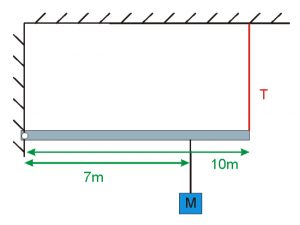
  1. A mass M = 120 kg hangs from a beam which is held by a cable.
    1. What is the tension T in the cable?
    2. Does the wall exert any force on the beam? Which one?
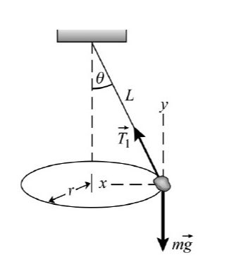
  2. A stone of mass 0.6 kg is forced to travel in a circle while it hangs from the ceiling, as shown in Figure. If the angle between the rope and the vertical is θ = 30º and the radius of the circle is r = 35 cm:
    1. What is the speed of the stone?
    2. What is the tension in the rope?
  3. A wheel of radius r = 80 cm has moment of inertia 10 kg m2. It is rotating around its central axis propelled by a rocket attached to a point on its outer rim. The rocket is expelling gas
    tangentially to the wheel, resulting in a constant force. Determine:

    1. The magnitude of the equivalent force, if we know that the wheel, starting from rest, reaches an angular speed of 1 rev/s in 6 s.
    2. The value of both tangential and normal acceleration in a point on the outer rim of the wheel.
    3. The angle that the total acceleration forms with the radius at that point.
    4. The time that the wheel takes to reach the same angular velocity, under the action of the same force, if we add a very thin ring of mass 5 kg around the outer rim.