Chapter 11. INTERNAL FORCES IN STRUCTURAL MEMBERS: ISOSTATIC PLANE BEAMS
11.1 Isostatic beams. Introduction.
11.2 Reactions at supports.
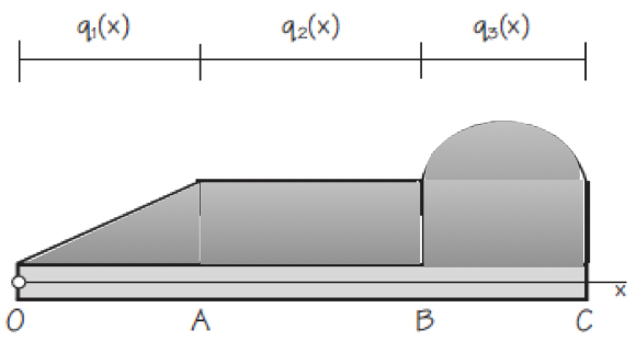
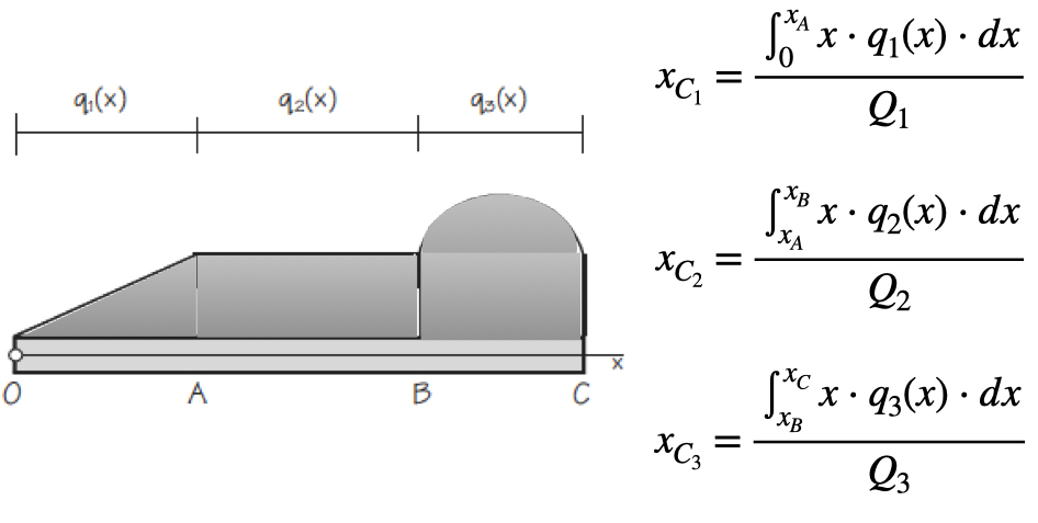
11.3 Types of loads on beams.
11.4 Internal forces in beams. Sign convention.
11.5 Loads, shears and axial forces.
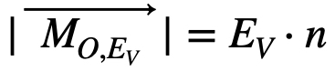
11.6 Bending moments.
11.7 Graphical analysis of a beam.
11.8 Elastic curve of a beam.
You should learn to solve any isostatic plane beam after the theoretical lectures, the problem sessions and the homework you did during this part of the subject. Chapter objectives can be summarized as follows:
- To show how to use the method of sections to determine the internal loadings in a member.
- To generate this procedure by formulating equations that can be plotted so that they describe the internal shear and moment throughout a member.
- To draw the shear and moment diagrams for any isostatic plane beam.
The next video explains how to solve a beam using the method of sections (Spanish from a Professor at the Universitat Politècnica de València).
https://media.upv.es/#/portal/video/74c39eb3-0e90-504d-80f2-9664a5f4b92a
Bibliography
Rodes Roca, J. J., Durá Doménech, A. i Vera Guarinos, J., Fonaments físics de les construccions arquitectòniques (Publicacions de la Universitat d’Alacant, Alacant, 2011). Capítol 12.
Rodes Roca, J. J., Exercicis i problemes dels fonaments físics d’arquitectura. I. Vectors lliscants i geometria de masses (ECU, Alacant, 2009)
Rodes Roca, J. J. i Durá Doménech, A., Exercicis i problemes dels fonaments físics d’arquitectura. II. Estàtica aplicada a les estructures (Col·lecció Joan Fuster 154, Universitat d’Alacant, 2013)
Tipler, P. A. i Mosca, G., Física per a la ciència i la tecnologia, Volum 1 (Reverté, Barcelona, 2010). Capítols 1 i 12.
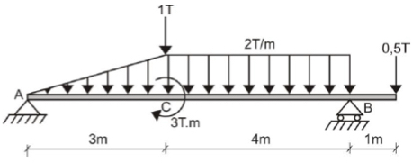
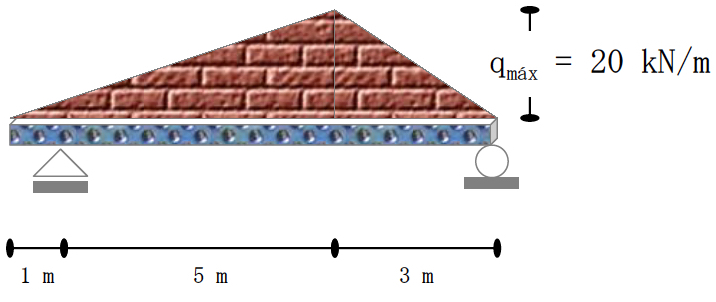
 EXERCISE 2: Draw the shear-force and bending-moment diagrams for the loaded beam and determine the maximum moment M and its location x from the left end.