After reading previous entry and understanding the meaning of distributed forces, how to calculate the equivalent resultant to the distributed load, you should try to solve next exercises.
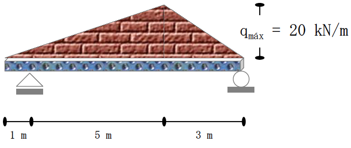
EXERCISE 1: Calculate the supports reactions at A and B for the beam subjected to the asymmetric load distributions.
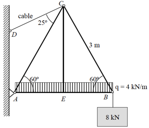
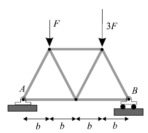
EXERCISE 2: The symmetric simple truss is loaded as shown. Determine the reactions at wall support A and the tension in cable CD.
In the previous sections we treated all forces as concentrated along
their lines of action and at their points of application. This treatment provided a reasonable model for those forces. Actually, “concentrated” forces do not exist in the exact sense, since every external force applied mechanically to a body is distributedover a finite contact area, however small.
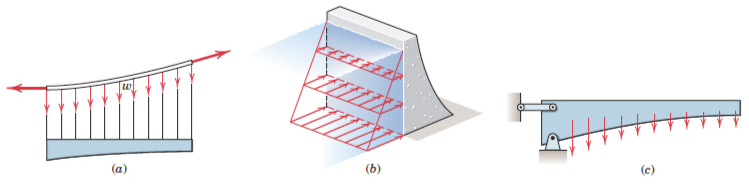
What is more, distributed forces are a particular case of a coplanar parallel system of forces. The body force due to the gravitationalattraction of the earth (weight) is by far the most commonly encountered distributed force. Figure shows (Meriam & Kreige 7th edition):
Line distribution: When a force is distributed along a line, as in the continuous vertical load supported by a suspended cable, Fig. (a), the intensity w of the loading is expressed as force per unit length of line, newtons per metre (N/m).
Area distribution: When a force is distributed over an area, as with the hydraulic pressure of water against the inner face of a section of dam, Fig. (b), the intensity is expressed as force per unit area. This intensity is called pressure for the action of fluid forces and stress for the internal distribution of forces in solids. The basic unit for pressure or stress in SI is the newton per square meter (N/m2), which is also called the pascal (Pa).
Volume distribution: A force which is distributed over the volume of a body is called a body force. The most common body force is the force of gravitational attraction, which acts on all elements of mass in a body. The determination of the forces on the supports of the heavy cantilevered structure in Fig. (c), for example, would require accounting for the distribution of gravitational force throughout the structure. The intensity of gravitational force is the specific weight ρg, where is the density (mass per unit volume) and g is the acceleration due to gravity. The units for ρg are (kg/m3)(m/s2) N/m3 in SI units
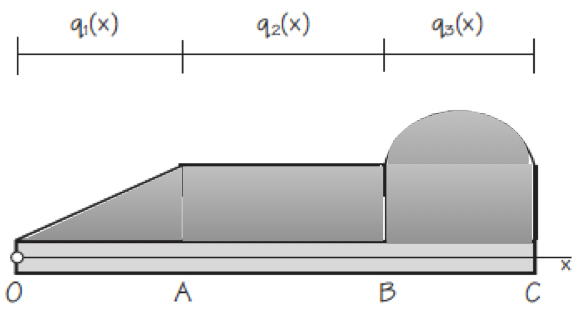
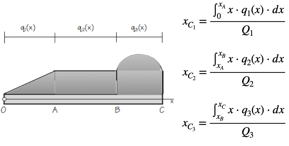
Figure shows a statically determinate beam that is supporting a general distributed load. The intensities qi(x) of a distributed load may be expressed as force per unit of length of beam. The intensity may be constant or variable, continuous or discontinuous. The intensity of the loading in Figure is constant from A to B and variable from O to A and from B to C. Although the intensity itself is not discontinuous at A and B, the rate of change of intensity dq/dx is discontinuous.Any distributed load can be replaced by a concentrated load with a magnitude equal to the area under the load curve and a line of action passing through the centroid of the area. Therefore, we need to determine the equivalent force of the distributed force, i. e. the resultant, and the centre of gravity where it will be applied. Once the distributed loads have been reduced to their equivalent concentrated loads, the external reactions acting on the beam may be found by a straightforward static analysis as developed in Chapter 6 (equilibrium).
After reading previous entry and understanding the meaning of stability, rollover and stabilising moments, you should try to solve next exercise.
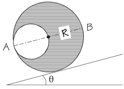
A homogeneous cylinder of radius R has a cylindrical hole of diameter R as shows in Figure. Cylinder can roll down the inclined plane without slipping. Determine the maximum angle θ of the inclined plane because the cylinder be in equilibrium. Obtain also the angle between the horizontal and the diameter AB in this situation.
NOTE:you can send your solution by tutorial tool in UACloud for including it in the continuous evaluation.
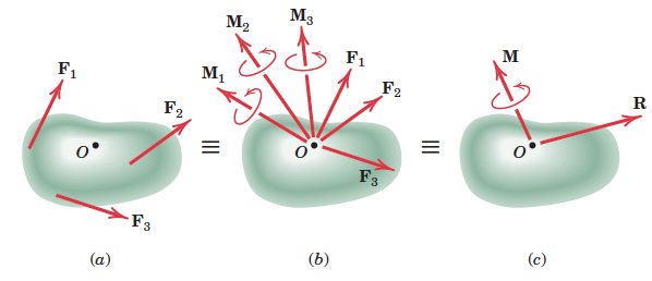
Any system of forces may be replaced by a resultant force R and a resultant moment (couple of a force) M at any point of the space. We call this couple vectors (R, M) as system “torsor”. Figure (from Meriam & Kraige 7th edition) shows a system of forces acting on a rigid body.
The point O selected as the point of concurrency for the forces is arbitrary, and the magnitude and direction of M depend on the particular point O selected. The magnitude and direction of R, however, are invariant, i.e. are the same no matter which point is selected.
If a system of forces acting on a body are such that the resultant force and resultant moment at point O are mutually perpendicular, the whole system can be replaced by a single force acting along a new line of action such that it causes the same moment with respect to O. We now examine the resultants for several special system of forces:
Concurrent forces: because there are no moments about the point of concurrency, system “torsor” at this point is only the resultant force R.
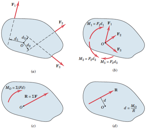
Parallel forces: not all in the same plane, the magnitude of the parallel resultant force R is simply the magnitude of the algebraic sum of the given forces. The position of its line of action is obtained from the principle of moments by requiring that r × R = MO. Here r is a position vector extending from the force–couple reference point O to the final line of action of R, and MO is the sum of the moments of the individual forces about O.
Coplanar forces: it may be reduced to only the resultant force R provided the line of action of R is passing through the centre of the system of forces, as shows Figure (rom Meriam & Kraige 7th edition):
STABILITY AND TOPPLING
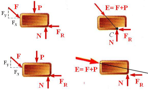
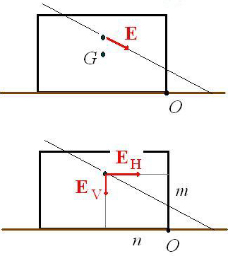
Let’s consider a 2D situation. A rigid body under the action of forces (which are necessarily coplanar) can only be in equilibrium if the system of forces seen in the free-body diagram can be reduced to three concurrent forces that meet at a point that is inside the body.
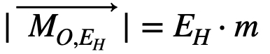
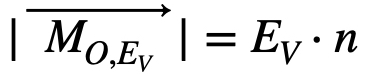
Three concurrent forces at point C which is inside the rigid body: EQUILIBRIUM (upper figure).Three non-concurrent forces inside the rigid body: THERE IS NO EQUILIBRIUM (bottom figure). Therefore, if a body is not in equilibrium, we can check if it is prone to overturning or stable against toppling. For this, we calculate the resultant of all external forces and draw it at the point where its line of action cuts the line of action of the weight. Assume the rigid body can rotate about point O, we call rollover moment the expression:
and stabilising moment the expression:
If the rollover moment is larger than the stabilising moment, the rigid body will turn over.
A rigid body is said to in equilibrium if the resultant of all forces and all their moments taken about any and all points are zero.
Free body diagram (FBD): depiction of an object with ALL the external forces acting on it.
Reactions coming from the supports: usually a body is constrained against motions using supports. It is essentially to correctly estimate the number and type of reactions that a support can provide.
A mass M = 120 kg hangs from a beam which is held by a cable.
What is the tension T in the cable?
Does the wall exert any force on the beam? Which one?
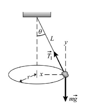
A stone of mass 0.6 kg is forced to travel in a circle while it hangs from the ceiling, as shown in Figure. If the angle between the rope and the vertical is θ = 30º and the radius of the circle is r = 35 cm:
What is the speed of the stone?
What is the tension in the rope?
A wheel of radius r = 80 cm has moment of inertia 10 kg m2. It is rotating around its central axis propelled by a rocket attached to a point on its outer rim. The rocket is expelling gas
tangentially to the wheel, resulting in a constant force. Determine:
The magnitude of the equivalent force, if we know that the wheel, starting from rest, reaches an angular speed of 1 rev/s in 6 s.
The value of both tangential and normal acceleration in a point on the outer rim of the wheel.
The angle that the total acceleration forms with the radius at that point.
The time that the wheel takes to reach the same angular velocity, under the action of the same force, if we add a very thin ring of mass 5 kg around the outer rim.
One of the most important magnitudes in architecture is the moment of a force or torque. And this magnitude will be extremely important in Chapter 5: Equilibrium.
Linear momentum, i.e. p = m·v, has a rotational analogue that it is called angular momentum, L. For a symmetrical object rotating about a fixed axis through the centre of mass (CM), the angular momentum is L = I·ω where I is the moment of inertia and ω is the angular velocity about the axis of rotation. The SI units for L are kg·m^2/s, which has no special name.
We saw in Chapter 2: Dynamics laws and applications that Newton’s second law can be written more generally in terms of momentum ΣF = Δp/Δt. In a similar way, the rotational equivalent of Newton’s second law which is Στ = I·α, can also be written more generally in terms of angular momentum Στ = ΔL/Δt where Στ is the net torque acting to rotate the object and ΔL is the change in angular momentum in a interval time Δt.
Angular momentum is an important concept in physics because, under certain conditions, it is a conserved quantity. If Στ = ΔL/Δt on an object is zero then ΔL = 0, so L does not change. This is the law of conservation of angular momentum for a rotating object:
The total angular momentum of a rotating object remains constant if the net torque acting on it is zero.
A video tutorial about rotation can be watched on the MIT-OCW webpage:
The symmetric simple truss is loaded as shown in Figure. Which force shown exerts the largest magnitude torque on the truss around point A? And around point B?
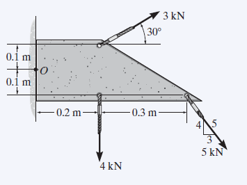
Calculate the net torque around point O due to the forces acting on the plate shown.
Video lecture: Rotational dynamic example
Problem set number 5
A wheel of radius r = 80 cm has moment of inertia 10 kg·m^2. It is rotating around its central axis propelled by a rocket attached to a point on its outer rim. The rocket is expelling gas
tangentially to the wheel, resulting in a constant force. Determine:
The magnitude of the equivalent force, if we know that the wheel, starting from rest, reaches an angular speed of 1 rev/s in 6 s.
The value of both tangential and normal acceleration in a point on the outer rim of the wheel.
The angle that the total acceleration forms with the radius at that point.
The time that the wheel takes to reach the same angular velocity, under the action of the same force, if we add a very thin ring of mass 5 kg around the outer rim.
If you have some doubts, you can watch next video related to rotational dynamic (Professor Michel van Biezen):
If you were satisfied with this example, you can check more video lectures on the webpage:
 EXERCISE 2: The symmetric simple truss is loaded as shown. Determine the reactions at wall support A and the tension in cable CD.